Panorama TF Range: Flexible Embedded Antennas for IoT Devices
Panorama Antennas has launched a family of five flexible PCB embedded antennas covering cellular 4G/5G, ISM 868/915MHz, and Wi-Fi 6E/7. All are ground-plane independent and designed specifically for OEM and space-constrained embedded applications.
About Panorama Antennas
Panorama Antennas is a UK-headquartered antenna manufacturer with a history stretching back to 1947. The company is best known for external vehicle and fixed-site antennas used in transportation, public safety, industrial IoT, and enterprise wireless applications. Its products are widely deployed with mobile network operators, system integrators, and OEMs globally.
The TF range marks Panorama’s formal entry into the flexible PCB embedded antenna segment – a market primarily served by smaller component specialists. The move makes sense given the growth in connected device production where engineers need certified, characterised RF components rather than in-house antenna designs.
Embedded Antennas in IoT Design
Embedded antennas – sometimes called internal or PCB antennas – are mounted directly inside a device enclosure rather than externally. For IoT hardware, this is increasingly the default approach. External SMA-terminated antennas add cost, require chassis penetrations, and introduce mechanical failure points in field-deployed equipment. An embedded flexible PCB antenna attaches via adhesive to a non-conductive internal surface, with a short coaxial pigtail connecting to the module’s U.FL port.
Flexible PCB (FPCB) antennas work best on non-conductive mounting surfaces. Placing them on or near metal chassis elements will detune them and degrade VSWR. Where metallic surfaces are unavoidable, a spacer or foam standoff is needed to create the required clearance.
The key technical advantage of the TF range is ground-plane independence. Conventional PCB trace antennas and chip antennas rely on the device motherboard’s ground plane as part of their radiating structure. This means antenna performance is difficult to predict without knowing the exact PCB layout. FPCB dipole designs like these operate independently of the host board geometry, which makes performance more consistent across different host devices – an important benefit for OEMs qualifying a single antenna design across multiple product variants.
The TF Range: Five Products
The initial TF launch comprises five antennas covering three technology segments: cellular (4G/5G and sub-1GHz ISM), and Wi-Fi. All share a common form factor philosophy – ultra-thin flexible PCB construction (1.6mm height), self-adhesive mounting, and a 1.13mm diameter C113 coaxial cable with a right-angle U.FL/MHF1 connector. Operating temperature range across the range is -40 to +80 degrees C.
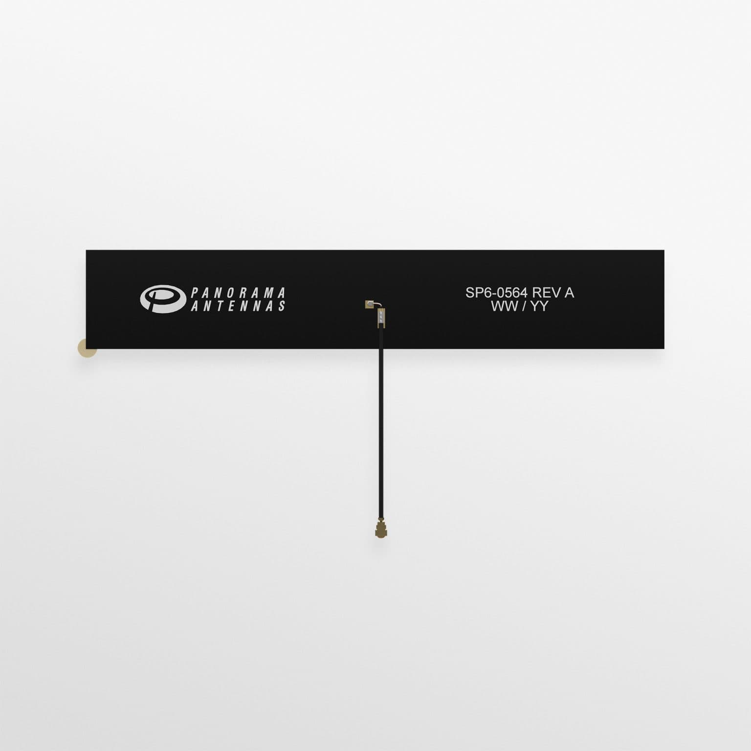
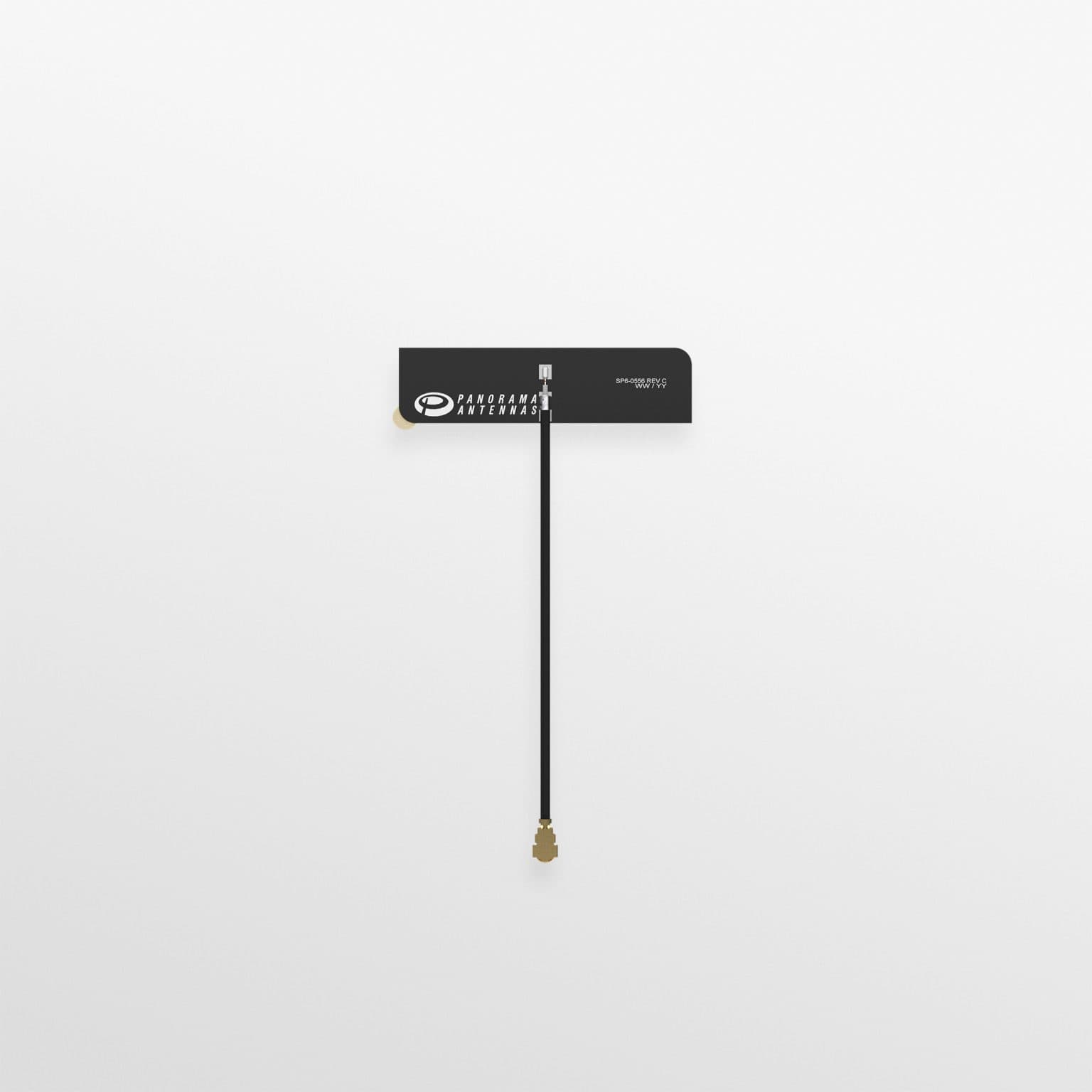
TFD-7-60 – 4G/5G Compact Flexible PCB Antenna
The TFD-7-60 is the core cellular entry in the range – a compact SiSo FPCB dipole covering global 4G and 5G frequencies. At 126 x 10mm, it is small enough to fit inside most industrial IoT enclosures, gateways, and smart metering devices. The dual-band design (698-960MHz and 1710-6000MHz) covers all major LTE and sub-6GHz 5G NR bands in use across Europe, North America, and Asia. This includes UK bands such as Band 20 (800MHz), Band 3 (1800MHz), and Band 78 (3.5GHz).
Applications include embedded cellular gateways, smart meters, EV chargers, industrial controllers, and any OEM device requiring 4G or 5G connectivity without an external antenna.
| Parameter | Value |
|---|---|
| Frequency Range | 698-960 MHz / 1710-6000 MHz |
| Antenna Configuration | SiSo (single input, single output) |
| Typical VSWR | <3:1 |
| Max Input Power | 5W |
| Dimensions (L x W x H) | 126 x 10 x 1.6 mm |
| Cable Type / Connector | C113 / U.FL (MHF1), right-angle |
| Cable Length Options | 50mm, 100mm, 200mm |
| Mounting | Adhesive or hook/loop |
| Operating Temperature | -40 to +80 degrees C |
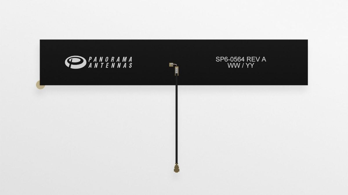
TFWB-6-60 – Wideband 4G/5G Flexible PCB Antenna
Where the TFD-7-60 starts coverage at 698MHz, the TFWB-6-60 extends this down to 617MHz. This makes it suitable for deployments requiring Band 71 (600MHz) coverage – primarily relevant in North American markets where T-Mobile and others use 600MHz for wide-area LTE/5G. The upper band extends down to 1427MHz, broadening coverage compared to the TFD-7-60.
The TFWB-6-60 is physically larger than its sibling at 146 x 25mm, which is the cost of the extended low-band performance. The wider PCB element is needed to achieve radiation efficiency at 617MHz. For most UK-focused deployments, the TFD-7-60 will suffice. The TFWB-6-60 is the better choice for global product variants where 600MHz band support is required.
| Parameter | Value |
|---|---|
| Frequency Range | 617-960 MHz / 1427-6000 MHz |
| Antenna Configuration | SiSo |
| Typical VSWR | <3:1 |
| Max Input Power | 5W |
| Dimensions (L x W x H) | 146 x 25 x 1.6 mm |
| Cable Type / Connector | C113 / U.FL (MHF1), right-angle |
| Cable Length Options | 50mm, 100mm, 200mm |
| Mounting | Adhesive or hook/loop |
| Operating Temperature | -40 to +80 degrees C |
TFD-868-915 – ISM 868/915MHz Compact Flexible PCB Antenna
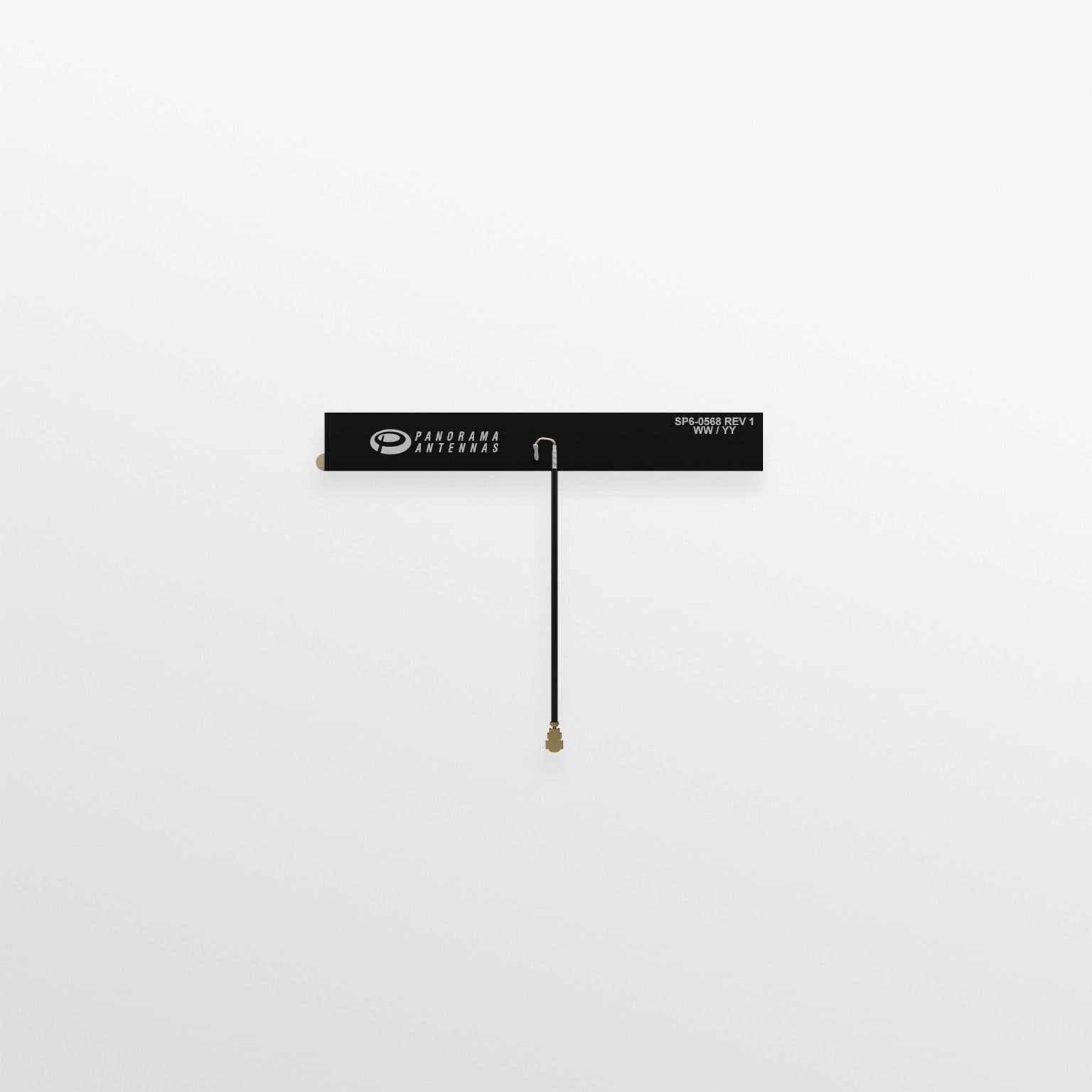
The TFD-868-915 covers the 863-928MHz band, making it the LPWAN antenna in the TF range. This covers both the European 868MHz ISM band (used by LoRaWAN, Sigfox, and wireless M-Bus in the UK and most of Europe) and the 915MHz band (used in the Americas and parts of Asia-Pacific). It is the smallest antenna in the range at 75 x 10mm – an important factor for compact IoT nodes where internal space is at a premium.
Target applications are smart metering, LoRaWAN end-nodes, wireless sensor networks, and any sub-1GHz IoT device where a whip or external antenna is undesirable. The omnidirectional radiation pattern and VSWR of <2.5:1 are consistent with what is expected from a well-designed PCB dipole at this frequency.
| Parameter | Value |
|---|---|
| Frequency Range | 863-928 MHz |
| Pattern | Omnidirectional |
| Typical VSWR | <2.5:1 |
| Max Input Power | 5W |
| Dimensions (L x W x H) | 75 x 10 x 1.6 mm |
| Cable Type / Connector | C113 / U.FL (MHF1), right-angle |
| Cable Length Options | 50mm, 100mm, 200mm |
| Mounting | Adhesive or hook/loop |
| Operating Temperature | -40 to +80 degrees C |
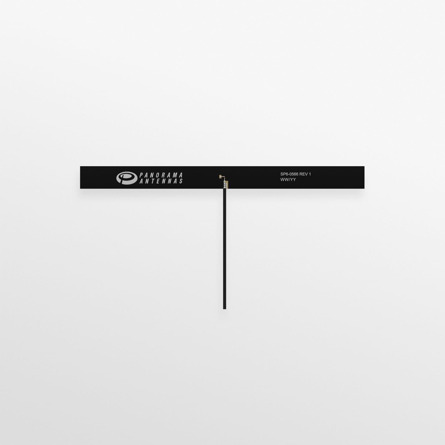
TFD-24-58-72 – Wi-Fi 6E/7 Flexible PCB Antenna (SiSo)
The TFD-24-58-72 is the single-stream Wi-Fi embedded antenna in the range, covering 2400-2485MHz and 5150-7125MHz. The upper band range – extending to 7125MHz – means this antenna supports the 6GHz band introduced with Wi-Fi 6E and carried forward in Wi-Fi 7. It also supports Bluetooth, which shares the 2.4GHz spectrum. At 35 x 9mm, this is the most compact antenna in the entire TF range.
For IoT applications, this is relevant to Wi-Fi connected devices such as smart home controllers, industrial wireless gateways, EV charge points with local Wi-Fi interfaces, and connected consumer devices being designed with future-proofed Wi-Fi 6E capability.
| Parameter | Value |
|---|---|
| Frequency Range | 2400-2485 MHz / 5150-7125 MHz |
| Antenna Configuration | SiSo |
| Typical VSWR | <2.5:1 |
| Max Input Power | 5W |
| Dimensions (L x W x H) | 35 x 9 x 1.6 mm |
| Cable Type / Connector | C113 / U.FL (MHF1), right-angle |
| Cable Length Options | 50mm, 100mm, 200mm |
| Mounting | Adhesive or hook/loop |
| Operating Temperature | -40 to +80 degrees C |
TFM2-24-58-72 – Wi-Fi 6E/7 Flexible PCB Antenna (2×2 MiMo)
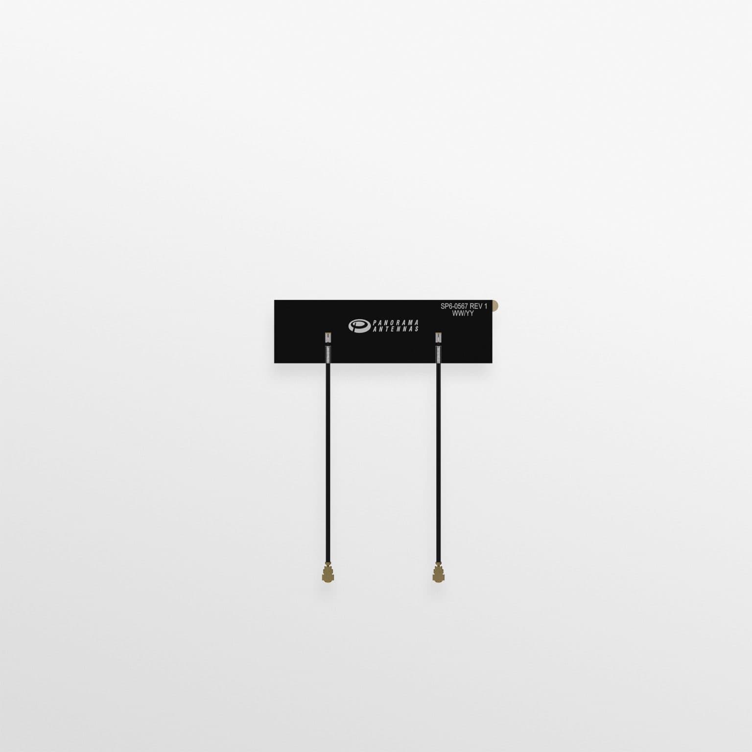
The TFM2-24-58-72 pairs two antenna elements in a single flexible PCB to deliver 2×2 MiMo Wi-Fi capability. It covers the same 2400-2485MHz and 5150-7125MHz range as the TFD-24-58-72 SiSo model, but the dual-element construction enables spatial multiplexing and improved throughput on Wi-Fi 6E and Wi-Fi 7 connections. This matters in applications where the device needs sustained high-bandwidth local connectivity – edge gateways with local network offload, for example.
The practical benefit over using two separate TFD-24-58-72 units is integration. A single MiMo antenna board is easier to manage in manufacturing and reduces routing complexity. At 55 x 16mm, the TFM2 is only marginally larger than the SiSo TFD variant, making the space trade-off straightforward for most enclosures.
| Parameter | Value |
|---|---|
| Frequency Range | 2400-2485 MHz / 5150-7125 MHz |
| Antenna Configuration | 2×2 MiMo |
| Typical VSWR | <2.5:1 |
| Max Input Power | 5W |
| Dimensions (L x W x H) | 55 x 16 x 1.6 mm |
| Cable Type / Connector | C113 / U.FL (MHF1), right-angle (x2) |
| Cable Length Options | 50mm, 100mm, 200mm |
| Mounting | Adhesive or hook/loop |
| Operating Temperature | -40 to +80 degrees C |
Range at a Glance
The five TF products cover distinct use cases with no overlap. The selection logic is straightforward.
| Model | Technology | Frequency | Size (mm) |
|---|---|---|---|
| TFD-7-60 | 4G/5G SiSo | 698-960 / 1710-6000 MHz | 126 x 10 |
| TFWB-6-60 | 4G/5G Wideband SiSo | 617-960 / 1427-6000 MHz | 146 x 25 |
| TFD-868-915 | ISM / LoRa / LPWAN | 863-928 MHz | 75 x 10 |
| TFD-24-58-72 | Wi-Fi 6E/7 SiSo | 2400-2485 / 5150-7125 MHz | 35 x 9 |
| TFM2-24-58-72 | Wi-Fi 6E/7 2×2 MiMo | 2400-2485 / 5150-7125 MHz | 55 x 16 |
What This Means for IoT Designers
Panorama entering the embedded antenna market gives IoT hardware teams a well-known name to put on a BOM alongside their cellular module or Wi-Fi chipset. The RF engineering and testing infrastructure behind a company like Panorama means these are characterised, documented parts – not generic unbranded components from a catalogue. That matters for regulatory submissions and for customers who scrutinise supply chain quality.
The FPCB dipole format is also increasingly preferred over chip antennas in demanding environments. Chip antennas are sensitive to their surrounding PCB layout and to adjacent components. FPCB dipoles are more forgiving and their performance is better defined, which reduces the risk of antenna re-work during hardware bring-up.
All five antennas are available in three cable lengths (50mm, 100mm, 200mm) with U.FL termination, which is the standard connector on most cellular and Wi-Fi modules. Datasheets and installation instructions are available from Panorama’s website. Sample requests and pricing are handled through the standard Panorama quoting process.
For a broader look at antenna selection for cellular IoT applications – including how to choose between internal and external antennas for different deployment scenarios – see our IoT Antenna Directory and Antennas & RF guides.
Related reading